

Weekly Hardware
Week 1: Planar Exact Constraint Mechanism
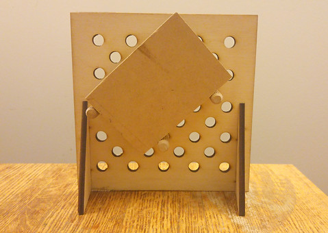
This is the planar exact constraint system that I built and tested.
The Process:
Based on the initial sketch of the prototype, I headed to the HobbyShop to look for any scrap materials I could use, to build my prototype. I found wooden sheets, some MDF board and few half inch pegs. After some quick measurements and changes to my sketch, I used SolidWorks to quickly model the face of the board with holes. The dimensions of plane were 8"x8". I used the Fill tool to stagger holes at 45deg and 1" apart. With the DXF file of the face, I hoped to be able to guide the mill spindle with a drill chuck to various positions to drill holes.


Following this, I used the radial saw to cut out a 5"x3"x1" block of MDF so serve as my object to be constrained. I now had all the pieces I needed to play with my planar exact constraint system.


Playing with my system was fun and it shed light on certain nuances of the problem. I wondered how the sensitivity of the system would change if the block had curved edges or unusual geometries. Overall, the exercise was very useful in improving my intuitive feel for designs involving planar constraints.
As the milling machines were occupied, I decided to use the Laser Cutter instead. I used a thinner stock of wood (0.25") to ensure that the laser would be able to penetrate the material. Aware that while cutting out holes with the laser, the burn radius would enlarge them, I test cut a hole a couple of times with reduced/"toleranced" dimensions until I obtained a nice fit. I updated the DXF file of the plane and added a couple of rectangular slots on eigher side, to slot in supports to prop the structure. In hindsight, I should have made T-slots in the supports to secure them onto the plane using nuts and bolts. Following this, I was ready to laser cut.